
 Automotive lighting plays a very important role to ensure a safe driving. New technologies are developing rapidly including extensive use of new light sources such as LED / LED modules, and “smart” automotive lighting systems such as automatic bending lighting, Headlamps alternately provide driving beam and passing beam and adaptive front-lighting system (AFS). These technologies deliver many advantages including better performance, reduced energy consumption, improved reliability, shorter ramp up time, anti-vibration and shock, small size and more design possibilities.
However, they also bring new problems. For LED light sources, sensitive thermal characteristics influence the stability of photometric performance and UV-radiation from LED light sources may deteriorate light transmitting components. Therefor, thermal design, stability test, usage of low-UV-type LED module and UV-resistance test of internal materials become extra important. Newer versions of ECE Regulation No. 6, No. 7 for signal lamps require one minute and thirty minutes photometric tests for light sources other than filament lamp(s). Also, new ECE Regulation No. 112 introduces a set of tests for LED modules including color rendering measurement, UV-radiation measurement and temperature stability tests.
For these “smart” lighting systems, more complex structures and lighting “modes” are also introduced. In a recent version of ECE Regulation No. 112 and No. 123, mechanical, electromechanical or other device for headlamps alternately require that driving beams and passing beams or bend lighting is required to withstand endurance tests and function failure tests.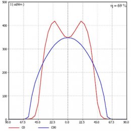 For AFS, different “modes” are defined-Class C, E, V, W for passing beams: each system shall provide a Class C passing beam and one or more additional class (es), and each class should fulfill the photometric requirements specified in ECE Regulation No. 123.
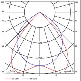
Technology for photometry measurement is developing very fast, Goniophotometers for general lighting and light sources can be used to create
a model of 3-D light intensity distribution fast and accurately. The model can be imported into simulating and design software such as TracePro, Zemax, DIAlux and other CAD software using an electrical file format such as .ies, CIBSE and .ldt.Most LED suppliers input the light intensity distribution information (Light Distribution Curve) into the product datasheet. Therefore, more precise, controllable and personalized designs are possible.
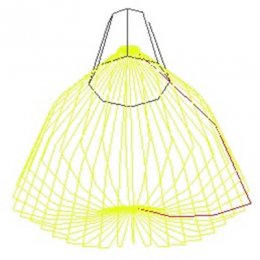
Figure 1. Light Distribution Curve
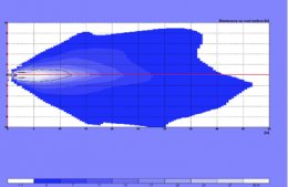
When designs become versatile and personalized, more accurate photometry measurement methods to verify the prototype’s photometric performance should be introduced. Advanced Goniophotometers for automotive lighting can be used to verify the performance using scan mode even with 0.01° accuracy in both axis. Detailed datasheet and light intensity distribution file are generated and the electrical file can be imported into optical design software to analyze and eventually improve the design. Figure 2: Isoline diagram measured and generated by automotive lighting photometric measurement system (LMT GO H1400, LMT LIMES 2000 software). Figure 3: Illumination simulated by automotive lighting photometric measurement system (LMT GO H1400, LMT LIMES 2000 software)Regarding the
sensitive thermal characteristic of LEDs, thermal simulation software, thermocouples and IR cameras can be used to analyze and optimize the thermal design. Influenced by thermal accumulation and current variation both color and intensity of the light emitted will be changed. Thus, when performing thermal stability verification tests, both color and intensity values should be verified. A constant current circuit and pulse width modulation (PWM) solution is introduced. LED controllers is an important topic and design engineers should note that PWM solutions cause problems for light intensity measurement. In order to detect small and fast light intensity changes, the optical sensor is normally designed using a high sampling frequency. The integration time for each sample is very short. However, for PWM LED, s the light emitting frequency is much lower. The result is that the reading of light intensity will be randomly changed. To avoid this, some photometry measurement systems have integrated a special optical sensor—the PMW sensor, whereby the sampling frequency is lower and integration time is longer.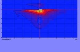
RELATED VIDEO

RELATED FACTS
-
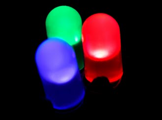 A light-emitting diode (LED) is a semiconductor light source. LEDs are used as indicator lamps in many devices and are increasingly used for other lighting. Introduced as a practical electronic component in 1962, early LEDs emitted low-intensity red light, but...
- UK Automotive Products Ltd (UKAP) is a supplier of heavy duty vehicle automotive lighting equipment based in Cannock, Staffordshire. Their product range includes bulb and light-emitting diode lighting - LED lamps, headlamps, lightbars, beacons, direction indicators...
- Photopia is a non-imaging optical design and analysis program written and distributed by LTI Optics, LLC (formerly Lighting Technologies, Inc.) since 1996. Photopia's main market is the architectural lighting industry but it is also used in the automotive, medical...
Share this Post
latest post
-
 Car design.com June 14, 2026
 -
 Automotive power supply Design May 25, 2026
 -
 Become a car Designer May 5, 2026
 -
 Car Design software online April 15, 2026
 -
 Car Designs March 26, 2026
 -
 Automobile, Vehicle March 6, 2026
 -
 Automotive Shop Design February 14, 2026
 -
 Cars Design January 25, 2026
 -
 Top Automotive Design Schools January 5, 2026